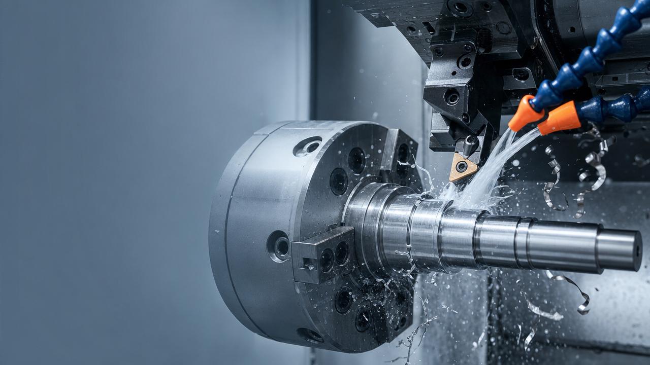
A turning center can look like an obvious match on paper: the quoted swing clears the part, the maximum spindle speed seems generous, and the motor rating exceeds that of the machine being replaced. Then the actual setup introduces a long boring bar, a hard-to-cut alloy, or a tight diameter tolerance after an hour of continuous production. The comfortable margin begins to disappear.
Choosing CNC turning centers requires a closer look at how spindle power and torque meet the cutting load, whether usable capacity accommodates the complete setup, and how rigidity and thermal behavior affect the finished part. For technical evaluators, the most useful specification is not necessarily the largest number in a brochure. It is the one that remains meaningful at the speed, position, and duty cycle where the machine will work.
Start with the part, not the machine envelope
Before comparing models, define a representative production task. Include the material and its condition, starting stock form, finished dimensions, critical tolerances, surface finish, expected annual volume, and the operations needed before and after turning. A family of parts may require several representative setups rather than one nominal workpiece.
Separate the features that establish machine size from those that establish machine capability. A long shaft may dictate distance between centers and tailstock support, while a smaller aerospace component may be more demanding because of material removal, bore access, and geometric tolerance. Automotive work may place less emphasis on a single difficult cut but much more on cycle time, repeatability, and automated loading.
Identify the limiting operation before approaching suppliers. If the deepest bore requires a long tool overhang, for example, that operation may determine the machine and tooling requirements more effectively than the outside diameter does. Share the actual drawing and proposed process, subject to any confidentiality or export-control restrictions, so that the discussion moves beyond catalog comparisons.
Spindle power and torque: read the curve, not just the peak
Spindle power describes the rate at which work can be done; torque describes the rotational force available at the spindle. Both matter, but their importance changes with cutting speed. Large-diameter turning and heavy interrupted cuts often need substantial torque at relatively low rpm. Small-diameter finishing can depend more on reaching and maintaining higher spindle speeds.
The relationship is straightforward: power increases with torque and rotational speed. In metric units, spindle power in kilowatts is approximately torque in newton-metres multiplied by rpm and divided by 9,550. This relationship is useful for checking whether a proposed cut falls within the spindle’s operating range, although the actual cutting demand also depends on material, tool geometry, depth of cut, feed, and process efficiency.
A peak motor rating alone does not answer the production question. Ask for the spindle power and torque curves, including continuous and short-duration ratings, and check the speed ranges at which they apply. A spindle may advertise high peak power but deliver it only above the speed used for a large part. Likewise, a short-duty rating is not a substitute for continuous output during a long roughing cycle.
Match the spindle to the difficult cut
- Large diameters or tough alloys: Examine continuous torque at the intended cutting speed, as well as the effect of low-speed gearing or transmission arrangement.
- Small precision components: Check usable high-speed range, spindle runout under the specified test conditions, and the suitability of the workholding system at speed.
- Bar-fed production: Confirm the permitted speed and bar support arrangements for the actual stock, not just the spindle’s no-load maximum rpm.
- Driven-tool operations: Evaluate live-tool power, torque, and speed separately; the main spindle rating does not describe milling or drilling performance.
Leave room for tool wear, material variation, and conservative process changes, but avoid assuming that the largest motor will solve every problem. Chatter can arise from the tool, workpiece, fixture, or machine structure before the motor reaches its limit.
Capacity is more than swing and distance between centers
Published capacity figures help narrow the field, but they rarely describe the complete working envelope. Swing over the bed is a clearance measure; it is not necessarily the maximum diameter that can be machined with the chosen turret, toolholder, chuck, and part position. Compare it with swing over the carriage and the manufacturer’s stated maximum turning diameter.
For length, account for the chuck or collet, jaw projection, part engagement, tailstock or subspindle position, and tool approach. A nominal distance between centers does not automatically translate into the same usable machining length. On a long component, steady-rest location and tool access may become decisive.
Request a layout drawing or simulation of the most restrictive setup. Include open and closed jaw positions, tool changes, tailstock movement, and part transfer if a subspindle is involved. This exercise can reveal collisions or lost travel before they become expensive shop-floor discoveries.
What tolerances can the turning center hold in production?
A machine’s positioning accuracy and repeatability are useful indicators, but neither is a guarantee that a finished part will meet its drawing tolerance. The result also depends on workholding, tool condition, cutting forces, coolant, measurement method, operator practice, and temperature. A part can be dimensionally correct after a single finishing pass yet drift as the spindle and machine structure warm up.
Begin by identifying which tolerances matter most: diameter, roundness, cylindricity, straightness, bore-to-outside-diameter concentricity, or a geometric tolerance referenced to specific datums. Each places different demands on the process. A tight bore may be governed by boring-bar stiffness and chip evacuation, while coaxial features machined in separate setups may be dominated by workholding and transfer error.
Discuss the following with the supplier before treating a published accuracy figure as a purchasing criterion:
- Test definition: Which axis, measurement standard, travel range, and environmental conditions apply? Are figures supplied as measured values or specified limits?
- Thermal behavior: What warm-up procedure is recommended, and how are spindle, coolant, and ambient temperature changes managed?
- Structural stability: How will the proposed workholding, tool overhang, and cutting forces affect the critical feature?
- Process control: Are in-process probing, tool monitoring, or offset adjustments available and appropriate for the part?
- Verification: What measurement equipment and inspection method will be used to judge the result?
For a demanding application, arrange a cutting trial using representative material, tooling, workholding, and cycle conditions. Agree in advance on the features to inspect, sample quantity, warm-up state, run duration, and acceptance criteria. A small run cannot establish long-term process capability by itself, but it can expose problems that a static specification cannot.
Configuration choices that change the process
Not every component belongs on a conventional two-axis lathe. The right configuration depends on how many operations can be combined without sacrificing access, stability, or inspection control.
A two-axis turning center is often a practical choice for rotational parts that need external and internal turning. Adding a C-axis and live tooling allows operations such as cross-drilling, off-center holes, and milling flats, potentially reducing transfers to another machine. A Y-axis can extend access for off-center milling, although its usable travel and tool clearance should be checked against the actual features.
A subspindle can support second-side machining in one automated sequence, but transfer accuracy, gripping surfaces, and chip control deserve scrutiny. For long, small-diameter parts, a Swiss-type machine may offer better support near the cutting zone; stock preparation, guide-bushing requirements, and the part’s length-to-diameter ratio should be included in the evaluation.
More axes and stations can remove setups, but they also add programming, tooling, maintenance, and potential collision paths. Calculate the value of the complete process rather than counting functions. A separate operation may remain preferable when it protects a critical datum, simplifies inspection, or keeps a high-volume turning cell running consistently.
Evaluate the production system around the spindle
The cutting area is only part of the investment. Chip shape and evacuation can decide whether unattended operation is realistic, particularly with ductile materials or deep bores. Check the proposed chip conveyor, coolant filtration, tank access, and the routing of chips away from ways, sensors, and transfer zones. High-pressure coolant may help certain processes, but its benefit depends on the material, tooling, and operation.
Automation should be sized to the part family and production rhythm. A bar feeder suits compatible bar stock; a robot or gantry may be more appropriate for discrete blanks. Confirm loading clearances, gripper access, door interface, part orientation, and how rejected parts will be handled. Also consider what happens when a tool breaks or a chip nests around the chuck: an unattended cell needs a defined recovery strategy, not just a loading device.
Control and integration details matter as well. Review available CNC functions, postprocessor support, probing cycles, data interfaces, and the skills required for programming and maintenance. For international installations, verify local service coverage, spare-parts availability, electrical requirements, and any applicable import or export restrictions on the machine and its control components.
A practical way to compare shortlisted machines
Build a comparison around the same representative parts and assumptions. Give each supplier the material, stock condition, drawings, required output, tooling preferences, and inspection requirements. Ask them to identify the proposed workholding, cycle sequence, cutting conditions, and any operations excluded from their estimate. A faster quoted cycle is less persuasive if it omits deburring, measurement, part transfer, or tool-change allowances that another proposal includes.
Separate non-negotiable requirements from preferences. Required bar capacity, a critical bore tolerance, or a limit on floor space may eliminate a machine outright. Other factors—additional turret stations, extra automation, or higher spindle speed—should be weighed against their contribution to throughput, flexibility, and operating cost.
The strongest choice is the turning center whose capacity, spindle characteristics, and verified process performance align with the work it will actually see. A clear specification and a well-defined trial turn the purchase decision from a comparison of headline numbers into a test of production readiness.
Want to dive deeper into these market dynamics, or need data-driven support for your next business move? Drop a line below and let the analysts at AMTS provide customized insights.
We respect your privacy. Your information is strictly confidential.
Product Recommendations
 Abrasive Delivery SystemsIndustrial Waterjet Cutters: Abrasive Costs That Erode MarginsAnalyst :5-Axis Machining Scientist
 All-Electric Press BrakesAll-Electric Servo Drives: Energy Savings vs Upgrade CostAnalyst :Precision Turning Architect
 All-Electric Press BrakesReal-Time Angle Compensation: What It Fixes and What It Doesn'tAnalyst :Precision Turning Architect
 Latest Sector NewsHigh-Strength Steel Machining: Tool Life Myths to AvoidAnalyst :Dr. Alistair Vaughn
 3D 5-Axis LaserComposite Material Cutting Without Delamination: Key MethodsAnalyst :
 Robotic Bending CellsAutomated Sheet Metal Forming: Hidden Setup Costs ComparedAnalyst :Precision Turning Architect