Select a precision sheet metal fabrication supplier by the evidence it provides for finished-part accuracy: comparable production results, a credible process plan, and inspection methods tied to functional datums. A quoted tolerance has limited value unless it applies to the specified material, geometry, finish, and production quantity. Accurate flat blanks alone do not establish that formed assemblies will fit.
The strongest candidates identify difficult features before quoting, distinguish routine capability from special processing, and explain how variation will be controlled after bending, hardware installation, welding, and coating. Their quotation makes acceptance conditions explicit. This allows dimensional performance, lead time, and price to be compared on the same basis.
Start with the dimensions that determine fit
A drawing with uniformly tight tolerances often conceals the actual requirement. Mounting-hole relationships, connector openings, sealing surfaces, and mating flanges deserve different treatment from cosmetic edges. Establish which dimensions govern assembly, which protect clearance, and which merely describe the overall shape. Broadly tightening every dimension adds inspection and processing work without necessarily improving fit.
Consider a bent enclosure with holes on opposing walls. Hole spacing within each flat wall is largely established during cutting. The relationship between holes across the enclosure also depends on bend position, bend angle, material thickness, and springback. A supplier demonstrating precise hole cutting has answered only part of the capability question.
Datum selection should reflect how the part locates in service. If an enclosure seats on a base and locates against a side face, inspection from unrelated outside edges can produce acceptable measurements while concealing an assembly problem. Drawings and inspection plans need a common reference system that represents the functional interfaces.
Define the condition in which the part must meet its requirements. A flexible panel measured freely on a table can differ from the same panel supported or restrained in its installed position. Any required restraint belongs in the acceptance documentation, including support locations and clamping conditions. Unspecified clamping creates room for disagreement and can conceal distortion.
Separate cutting accuracy from formed-part capability
Equipment lists establish available processes, but they reveal little about repeatable results on a particular component. A laser cutting machine’s positioning specification does not describe finished feature accuracy across every material and thickness. Heat input, sheet condition, cutting parameters, burr formation, and subsequent deburring all affect the delivered edge.
Small holes require particular attention when their diameter approaches the sheet thickness. Edge quality, taper, and dimensional consistency become more demanding, and a cut hole may not provide the bearing or locating surface required by the design. Where function warrants it, drilling or reaming after cutting provides a different process route. That additional operation must appear in the quotation and inspection plan.
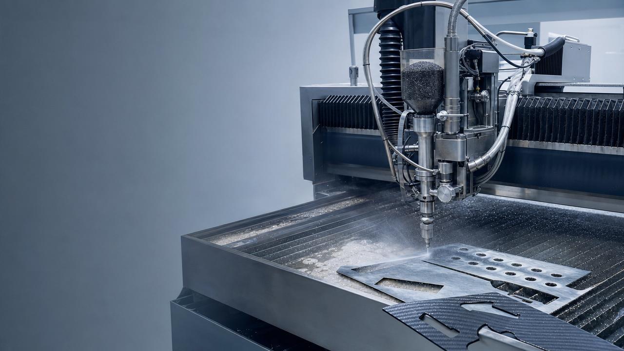
Waterjet cutting avoids a thermal heat-affected zone, but its capability still depends on kerf taper, cutting speed, material, and thickness. Punching introduces its own concerns, including burr direction, tool wear, and distortion around densely spaced features. Process selection should follow the feature’s functional requirements rather than a general ranking of technologies.
Bending demands evidence from comparable geometry. Long flanges magnify the positional effect of angular variation. Short flanges, features close to bend lines, and tight internal clearances constrain tooling and bend sequence. A part that appears straightforward in a flat drawing can require special tools or an additional setup once tool access is considered.
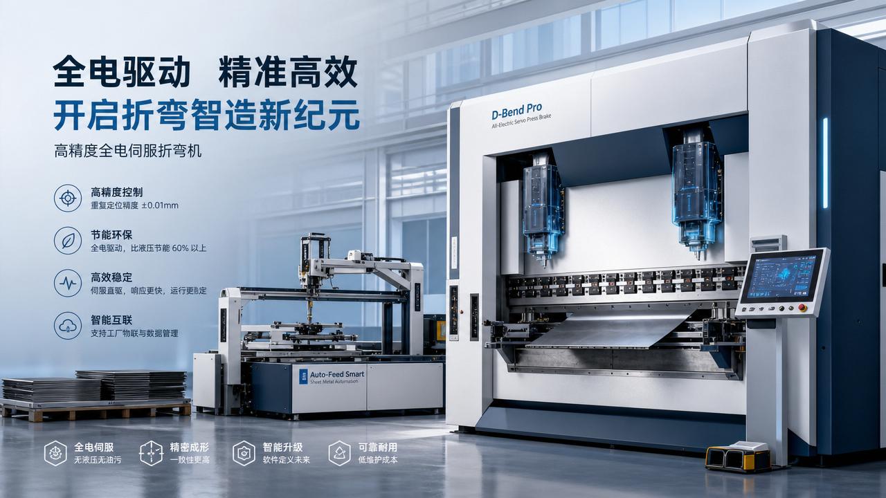
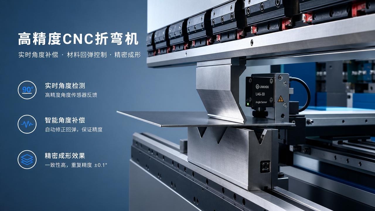
Ask for the proposed bend sequence, tooling approach, and treatment of springback-sensitive features. A useful response explains where angle correction occurs, how the first setup is approved, and which dimensions receive attention during production. A statement that a press brake has automatic angle measurement does not establish control of flange length, hole location, or the complete tolerance stack.
Material control belongs in the tolerance discussion
Specifying only “aluminum” or “stainless steel” leaves major forming variables unresolved. Alloy, temper or condition, thickness range, surface condition, and rolling direction influence bend behavior. Substituting material with a similar commercial description can change springback, achievable bend radius, and cracking behavior.
Thickness variation affects tooling contact and the relationship between the flat pattern and the formed dimensions. A bend program validated on one material lot needs confirmation when incoming stock changes. Evidence of material identification, lot traceability where required, and first-piece verification is more useful than an assurance that the same machine program will always produce the same result.
The supplier should also explain who controls flat-pattern development. Bend deductions are tied to the material and tooling combination used. If a supplied flat pattern is treated as authoritative while the forming process uses different assumptions, finished dimensions can drift even when the cut blank matches its file exactly.
Resolve that responsibility before release: whether the formed model governs, whether the supplier may adjust the blank, and how those adjustments are recorded. Changes to a flat pattern must preserve the approved finished geometry and remain connected to the correct drawing revision.
Inspect the part as it will be delivered
Finishing changes the acceptance problem. Coating adds material to surfaces and reduces clearance inside openings; buildup is not necessarily uniform around edges or recesses. Welding introduces local heating and shrinkage, while hardware insertion can distort thin sheet or affect nearby features. Inspection performed before these operations cannot establish final compliance.
Measurement equipment must suit the feature. Calipers are useful for many accessible dimensions but provide limited evidence for complex positional relationships or flexible surfaces. Coordinate measurement, optical inspection, dedicated fixtures, and functional gauges answer different questions. The presence of a coordinate measuring machine alone does not establish a suitable inspection method.
For thin sheet, probing force and support arrangement can influence the result. For optical inspection, edge detection must distinguish the intended boundary from burrs, reflections, or tapered cut edges. Request an explanation of how the measurement method handles these effects when they matter to acceptance.
Measurement uncertainty also matters near a tolerance limit. An instrument’s display resolution is not its measurement uncertainty. Agree on the acceptance decision rule when uncertainty is significant relative to the allowed variation; otherwise, the same borderline part can receive different dispositions at shipment and receipt.
Use production evidence to test repeatability
A carefully adjusted prototype demonstrates feasibility. Repeat production requires control across setups, material lots, tooling condition, and production runs. Ask whether samples were made using the intended production route or received additional hand fitting, selective rework, or special inspection. Those interventions affect both cost and repeatability.
Comparable evidence should resemble the proposed work in material, thickness, bend complexity, feature relationships, and finishing sequence. Records for flat brackets offer limited support for a deep enclosure with opposing mounting faces. Confidentiality may prevent disclosure of customer drawings, but anonymized inspection records or a representative trial can still demonstrate relevant capability.
Where process capability indices are offered, examine the underlying measurements. The process must be stable before such indices support a meaningful capability judgment. Sample size, sampling period, measurement method, and the inclusion of different setups determine what the result represents. Data from a short, specially controlled run do not establish performance across routine production.
A trial order is most informative when it exercises the planned route through final finishing. Define the evidence required before it begins: identified samples, measured critical features, material records, and documentation of deviations or rework. Where the intended supply pattern involves repeated setups, a trial spanning separate setups provides more relevant evidence than a single uninterrupted run.
Compare quotations at the same acceptance level
Price comparisons become misleading when quotations contain different assumptions. One supplier may include post-form machining, final inspection, and protective packaging, while another prices cutting and bending with general dimensional acceptance. Resolve those differences before treating the lower quotation as a saving.
A useful quotation states which drawing revision governs, which tolerances are accepted, and which requirements need clarification or exceptions. It also identifies the condition of inspection, included secondary operations, and any tooling or fixtures required. Silence on a difficult dimension should not be interpreted as a demonstrated ability to hold it.
Cost reduction should begin with function. An oversized clearance opening may tolerate greater variation than a locating feature. A flange dimension could be relaxed if the mating assembly references a different surface. Conversely, loosening a dimension that controls connector alignment merely transfers cost into assembly adjustment or rejection.
Ask for alternatives with their consequences stated explicitly: a larger internal bend radius, repositioned holes, a different hardware installation sequence, or a machined locating feature. Accept changes only after confirming their effect on fit, strength, appearance, and interchangeability. The approved drawing must capture the decision before production begins.
Make the award conditional on a defined production baseline
A technically credible supplier can explain how accepted samples become repeatable production. That baseline includes the approved material, drawing revision, process sequence, tooling or fixture references, inspection method, and any agreed subcontracted finishing route. Relevant changes need a defined review path, especially when they alter a critical feature or its measurement.
Outsourced operations deserve the same scrutiny as internal ones. If coating or welding determines final accuracy, establish who owns final acceptance and how nonconforming parts are handled. An acceptable intermediate part does not resolve responsibility for a finished component that fails its drawing.
Packaging also belongs in the delivery specification for distortion-sensitive parts. Thin panels and projecting flanges can leave inspection correctly and arrive bent. Support points, separation between parts, and protection of functional surfaces should reflect the component’s geometry. Packaging approval is particularly useful when shipment condition could be confused with manufacturing variation.
Award the work when the supplier’s evidence connects the required dimensions to a controlled production route and a credible final inspection method. Any unresolved critical tolerance should remain an explicit qualification item, with agreed evidence required before full production release.
Product Recommendations
 Abrasive Delivery SystemsIndustrial Waterjet Cutters: Abrasive Costs That Erode MarginsAnalyst :5-Axis Machining Scientist
 All-Electric Press BrakesAll-Electric Servo Drives: Energy Savings vs Upgrade CostAnalyst :Precision Turning Architect
 All-Electric Press BrakesReal-Time Angle Compensation: What It Fixes and What It Doesn'tAnalyst :Precision Turning Architect
 Latest Sector NewsHigh-Strength Steel Machining: Tool Life Myths to AvoidAnalyst :Dr. Alistair Vaughn
 3D 5-Axis LaserComposite Material Cutting Without Delamination: Key MethodsAnalyst :
 Robotic Bending CellsAutomated Sheet Metal Forming: Hidden Setup Costs ComparedAnalyst :Precision Turning Architect