A machine may still be mechanically sound while its CNC control has become the weak link. Operators may be working around unreliable screens, limited memory, unavailable spare boards, poor diagnostics, or a program transfer process that interrupts production. At the same time, a full machine replacement may be difficult to justify when the iron, spindle, axes, and tooling remain capable of making acceptable parts.
A CNC control systems retrofit is justified only when the existing machine can support the new control architecture without creating hidden performance, safety, or integration problems. The central decision is not whether a modern control has more functions. It is whether the machine’s motors, drives, feedback, electrical design, PLC sequence, and application requirements can be migrated with a predictable scope—and whether the resulting improvement produces a credible financial return.
Start with the machine’s remaining mechanical capability
Control replacement cannot correct every source of poor machining. Before reviewing CNC features, establish whether the machine foundation is worth preserving. A retrofit is usually a stronger candidate when structural rigidity, way condition, ballscrew condition, spindle health, lubrication, and geometric accuracy are still within a recoverable range.
For example, an older vertical machining center may suffer from intermittent axis alarms and obsolete control hardware, yet still have a stable spindle, sound castings, and acceptable backlash after compensation. That machine may benefit materially from a control upgrade. A machine with worn guideways, severe spindle vibration, unreliable toolchanger mechanics, and thermal instability presents a different situation: new electronics may make it easier to diagnose faults, but they will not restore process capability on their own.
Collect evidence before defining scope. This should include recent maintenance history, scrap patterns, axis positioning results, backlash and repeatability observations, spindle load behavior, alarm records, and the condition of cables and cabinets. It is also useful to compare the machine’s actual output against the tolerances demanded by current parts, rather than against the accuracy stated in its original documentation.
Map compatibility beyond the CNC cabinet
The control is part of a larger motion and automation system. A retrofit proposal based only on the model of the old CNC is incomplete. Compatibility must be verified at the signal, power, communication, motion, and machine-logic levels.
Axis motors, drives, and feedback
The first major question is whether existing servo motors and drives can be retained. Retention can reduce project cost and wiring work, but it is not automatically the lower-risk choice. Legacy drives may use proprietary command formats, analog velocity references, resolver feedback, older encoder protocols, or unsupported tuning methods. A new controller may require interface hardware, and each interface adds another component that can complicate commissioning and future service.
Motor data should be recorded from nameplates and documentation: continuous and peak current, voltage, torque constants, maximum speed, brake requirements, feedback type, connector details, and thermal protection. Drive information should include command interface, fault outputs, enable sequence, regeneration arrangement, and available diagnostic access. Do not assume that a motor can be paired with a different drive simply because its nominal power rating appears similar.
Feedback devices deserve particular attention on machines expected to hold tight tolerances. Incremental encoders, absolute encoders, resolvers, glass scales, rotary encoders, and reference switches all influence homing, position recovery, and closed-loop behavior. Reusing aging linear scales may preserve a direct-position feedback scheme, but only if their signal quality, mounting condition, and resolution remain suitable. A control retrofit can expose marginal feedback hardware that the old system had merely tolerated.
Spindle and auxiliary motion
Spindle integration often determines whether a project remains straightforward or expands substantially. Identify the spindle motor type, amplifier or inverter model, speed command method, orientation function, encoder feedback, gearbox logic, and any rigid tapping requirements. A basic analog speed command may be manageable, while synchronized tapping, spindle orientation for tool changes, or constant surface speed may require reliable encoder signals and carefully configured control functions.
Also review less obvious axes and devices: quill motion, pallet changers, rotary tables, tailstocks, bar feeders, hydraulic clamps, coolant systems, chip conveyors, probing systems, and automatic tool changers. On a five-axis machine, rotary-axis kinematics, rotary tool center point functions, axis limits, brake logic, and calibration methods require much more scrutiny than on a standard three-axis mill. On a turning center, turret indexing and spindle synchronization can be equally critical.
PLC logic and machine-specific sequences
Most retrofit risk sits in the logic that makes the machine behave as a machine rather than as a collection of moving axes. The PLC controls lubrication interlocks, hydraulic pressure checks, tool-change sequences, door states, alarms, M-functions, spindle permits, clamping, and recovery behavior after a fault.
Original ladder files, electrical drawings, I/O lists, parameter backups, and operator manuals are valuable because they expose intended machine behavior. Their absence does not make a retrofit impossible, but it changes the estimate. Logic may need to be reverse engineered from wiring, observed sequences, and device testing. That work should be recognized as engineering effort, not treated as a minor installation detail.
Separate “can connect” from “can perform”
A system can be electrically connected and still fail the performance test that matters to production. The required test depends on the machine’s role. A mold component, an aerospace contour, a medical turned part, and a sheet-metal press brake program place different demands on interpolation, acceleration, surface finish, synchronization, and repeatability.
Ask for representative part programs early. They reveal requirements that a feature checklist misses: macro usage, custom M-codes, probing cycles, coordinate transformations, high-speed machining options, canned cycles, subprogram conventions, and program sizes. If CAM-generated code will be used, confirm that a validated postprocessor can produce code for the proposed control and machine configuration. The first acceptable dry run is not sufficient proof; prove the cycle elements that drive quality, throughput, and recovery.
Risk is concentrated in the interfaces and the shutdown window
Downtime is often the largest operational exposure. The physical installation may proceed quickly, but commissioning can extend when undocumented wiring, weak feedback signals, unexpected drive faults, or incomplete PLC behavior appears. A realistic plan distinguishes between known work and discovery work.
Before the machine is taken offline, archive every available program, parameter set, PLC file, electrical drawing, drive configuration, and alarm history. Photograph cabinets, terminal strips, connector labels, relay panels, and field devices. Create a cross-reference between existing I/O points and the proposed system. This record is useful not only during installation, but also when the machine must be supported years later.
Risk can be reduced through a staged acceptance approach:
- Confirm the mechanical baseline and define measurable performance requirements.
- Complete the electrical and signal inventory before finalizing the bill of materials.
- Review safety functions separately from normal machine sequencing.
- Build and inspect cabinets, cable sets, and interface assemblies before shutdown where practical.
- Commission in layers: power distribution, emergency-stop chain, I/O, individual axes, spindle, auxiliary devices, then full automatic cycles.
- Run representative programs under controlled conditions and document any parameter or logic changes required for acceptance.
Safety review cannot be assumed to transfer from the old control to the new one. Emergency stops, guard interlocks, safety relays or safety controllers, hydraulic and pneumatic safe states, axis braking, spindle stopping behavior, and restart prevention need to be tested in the completed configuration. Older machines may contain safety arrangements that are difficult to interpret from aged drawings, making field verification essential.
Supply continuity is another practical risk. The proposed CNC, servo drives, I/O modules, operator panel components, batteries, and communication accessories should have an identifiable support path. A retrofit intended to remove obsolescence should not replace it with a collection of difficult-to-source adapters or undocumented custom boards.
Calculate payback from avoidable losses, not from the retrofit price alone
The financial case should compare the retrofit with realistic alternatives: continued repair of the existing control, replacement with a new or used machine, or deferral. A low initial retrofit quote may become expensive if it omits drives, feedback replacement, spindle work, PLC reconstruction, safety modifications, operator training, or production interruption. Conversely, comparing the retrofit only with the purchase price of a new machine may overstate its value if the existing mechanical platform needs major restoration.
Build the assessment around the losses the project can credibly reduce. These may include recurring failures of unsupported electronics, time spent recovering programs and parameters, slow data transfer, manual setup caused by missing functions, scrap linked to unstable motion or unreliable feedback, and lost output during unplanned control faults. Separate these from problems caused by worn mechanics, inadequate tooling, poor fixturing, or weak programming practices. Only the portion reasonably addressed by the retrofit belongs in its return calculation.
A simple decision model uses four elements:
- Total project cost: hardware, engineering, installation, wiring, mechanical correction directly required by the retrofit, validation, training, and planned downtime.
- Annual avoidable cost: support expense, repair exposure, recoverable downtime, and process losses likely to improve after commissioning.
- Residual machine value: the useful service expected from the machine structure, spindle, and critical mechanisms after the project.
- Alternative cost and timing: the capital, lead time, qualification effort, and disruption associated with replacing the machine.
Do not treat theoretical productivity features as savings until the shop can use them. Faster block processing has value only where programs and machining strategies are constrained by the old control. Networking has value when it removes a real program-management bottleneck. Automation interfaces matter when the machine is actually scheduled to work with external equipment. The most defensible payback model uses conservative assumptions and explains each one.
When a retrofit should be narrowed, delayed, or rejected
Not every aging control should be replaced immediately. A limited refurbishment may be more appropriate when the failure is isolated, spare parts remain available, and the machine has a short remaining production role. A broader modernization may be needed when the electrical cabinet, motors, drives, feedback devices, and safety system are all nearing end of life; in that case, calling the project a simple control retrofit can hide its true scope.
Replacement deserves serious consideration when mechanical restoration is extensive, the machine cannot meet current part-envelope or throughput requirements, or critical functions cannot be replicated reliably. This is particularly relevant where a machine must support complex five-axis kinematics, demanding synchronized turning, or tightly integrated automation but lacks dependable documentation and a stable mechanical baseline.
The strongest retrofit decision is therefore evidence-based: retain what is proven, replace what is unsupported or performance-limiting, define every interface before shutdown, and validate the machine against the work it must actually perform. That approach turns a CNC control upgrade from an optimistic hardware purchase into a controlled engineering decision.
Product Recommendations
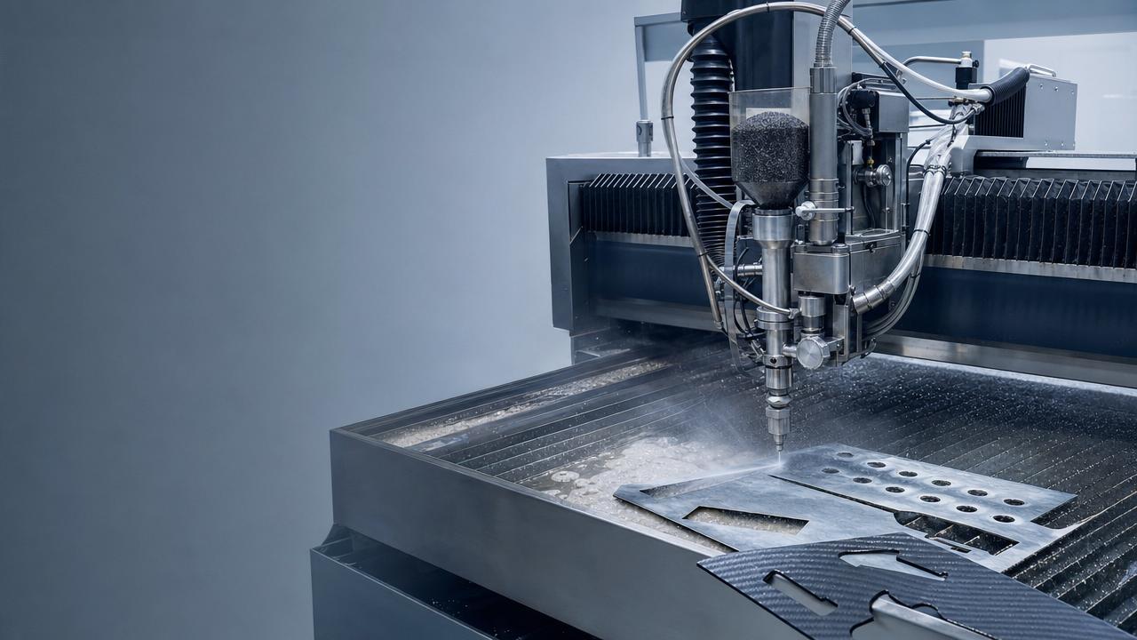
 Abrasive Delivery SystemsIndustrial Waterjet Cutters: Abrasive Costs That Erode MarginsAnalyst :5-Axis Machining Scientist
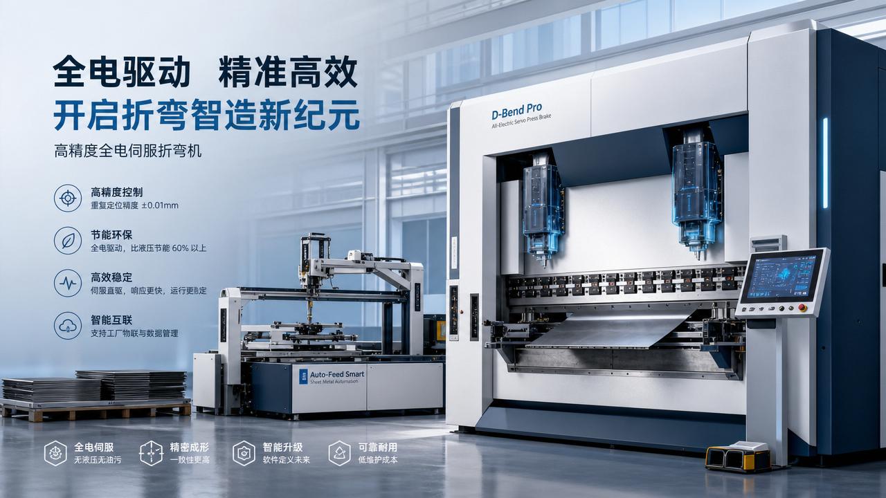
 All-Electric Press BrakesAll-Electric Servo Drives: Energy Savings vs Upgrade CostAnalyst :Precision Turning Architect
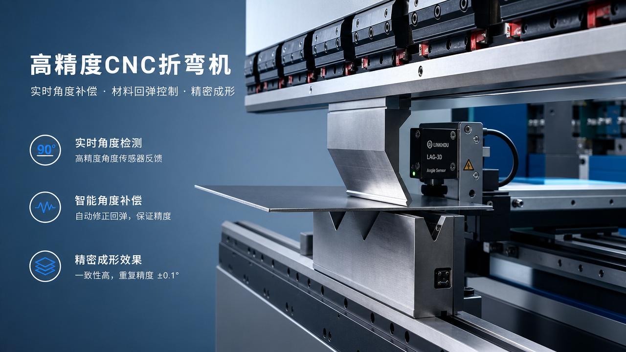
 All-Electric Press BrakesReal-Time Angle Compensation: What It Fixes and What It Doesn'tAnalyst :Precision Turning Architect
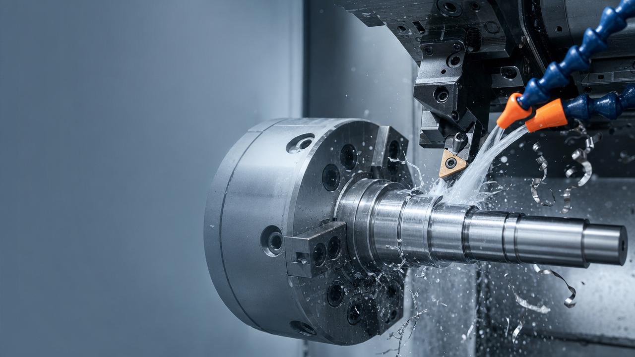
 Latest Sector NewsHigh-Strength Steel Machining: Tool Life Myths to AvoidAnalyst :Dr. Alistair Vaughn
 3D 5-Axis LaserComposite Material Cutting Without Delamination: Key MethodsAnalyst :
 Robotic Bending CellsAutomated Sheet Metal Forming: Hidden Setup Costs ComparedAnalyst :Precision Turning Architect